Services
Two main services — Revit MEP modelling and thermal CFD — plus engineering calculations and technical documents. Every job is scoped and quoted from your files.
Main service 1
CAD → Revit MEP modelling
Your 2D MEP drawings turned into a connected Revit model — HVAC, plumbing and electrical in one pass. Real Revit ducts, pipes, cable trays and fittings at the labelled sizes and heights, joined into systems.
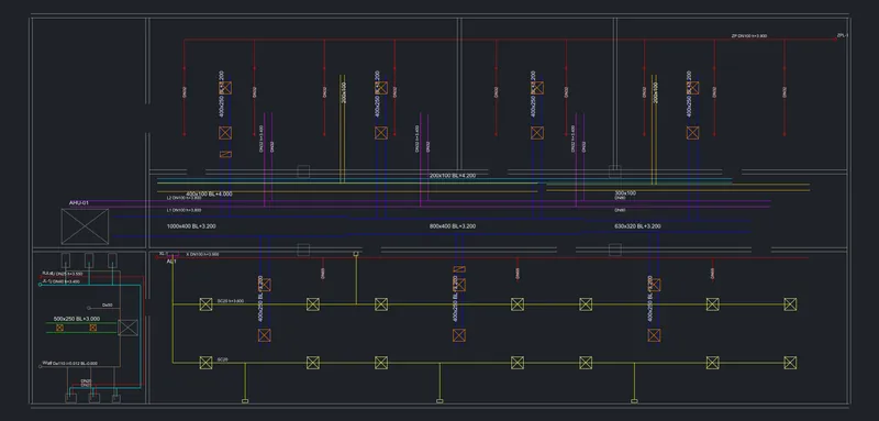
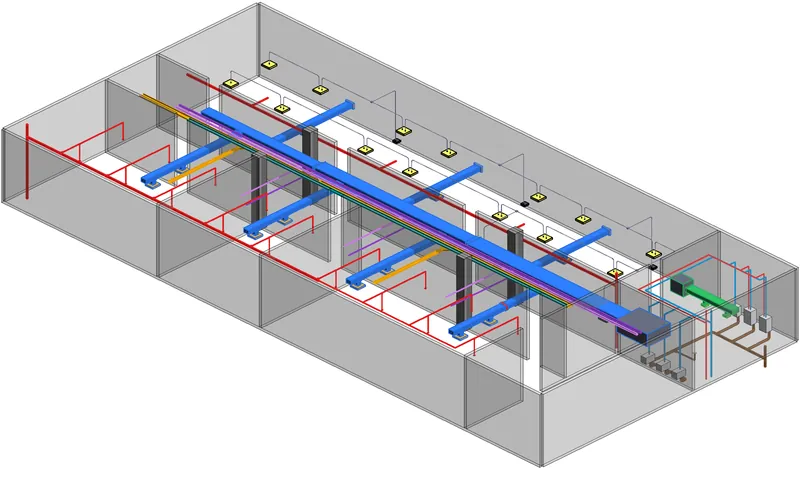
HVAC
- Rectangular and round ducts from double lines or centrelines
- Sizes 1000x400 / Ø400 and elevations (bottom, centre, top)
- Elbows, transitions, takeoffs, 45° offsets at height changes
- Fans / AHUs, dampers, diffusers and grilles with real connectors
- Supply / return / exhaust systems from layer names
Plumbing & fire
- Single-line pipes, DN / De / Ø labels; elbows, tees, crosses, reducers
- Cold & hot water, drainage, vent, chilled water, hydrant and sprinkler systems
- Risers from JL-1 / WL-1 / XL-1 symbols, run through every floor
- Drainage sloped to its stack (i=0.012 read from the drawing)
- Sprinkler heads with drops; WCs, basins, urinals, floor drains connected
Electrical
- Cable trays: power / low-voltage / fire kept separate
- Conduits SC / JDG / KBG / PC with bends and tees
- Lights, sockets and switches connected to their conduits
- Distribution boards and cabinets, conduits connected
- Coloured per service in the 3D views
Also from the same drawing: walls (door gaps kept), columns, arcs and angled runs. Several floors: one plan per storey, risers with the same tag join through all of them.
Read straight from your labels
1000x400 BL+3.200→ duct 1000 × 400, bottom at +3.200L1 DN100 h+3.800→ chilled water supply DN100, centre at +3.800400x100 BL+4.000on a tray layer → power tray 400 × 100
Your office's label standard is agreed at the start — no redrawing needed.
You receive
- Native Revit model (.rvt)
- Shaded 3D views (PNG)
- QA report: open ends, devices, assumptions
- Clash report: each clash with both elements and its location — 0 at delivery, or each one agreed with you
- Model accuracy report (when a reference model is supplied)
Good to know
- Models are built in Revit 2026; a Revit file cannot be opened in an older version.
- Clean drawings with labelled sizes and elevations give the best result; missing heights are agreed with you first.
- Your drawings stay confidential and are never used as samples.
Have drawings ready?
Send your DWG plans, the floors and systems in scope, and your deadline.
Main service 2
Thermal simulation & CFD
From your 3D model to a verified temperature field — modelling and thermal simulation for data centres, liquid cooling and heat-rejection equipment, solved in ANSYS Fluent.
Your 3D model
SolidWorks / STEP assemblies with thousands of parts, opened read-only.
CFD model
Equipment reduced to heat sources, fans and openings at their true size and position; bolts, cables and other flow-irrelevant detail removed.
Results
Temperature field, air paths, local hot spots and the inlet temperature of every unit.
Modelling rule: geometry that drives flow and heat transfer (openings, ducts, heat sources, obstructions) keeps its real dimensions; the rest is simplified — controlled mesh size, trustworthy results.
Data halls
- Hot / cold aisles, raised-floor supply
- Rack inlet temperatures vs. ASHRAE
- Cooling-unit failure (N+1), growth
Liquid cooling
- Cold plates and heat exchangers (CHT)
- Chip temperature, channel pressure drop
- Manifold flow distribution
Heat-rejection yards
- Dry-cooler / tower recirculation
- Wind, spacing, screen walls
- Layout comparison
Containers / modular
- Air flow and equipment cooling inside
- Inlet / exhaust arrangement
- Extreme-ambient checks
Typical physics: turbulence (k-ε / SST k-ω) · buoyancy · conjugate heat transfer · fans & porous media · steady / transient
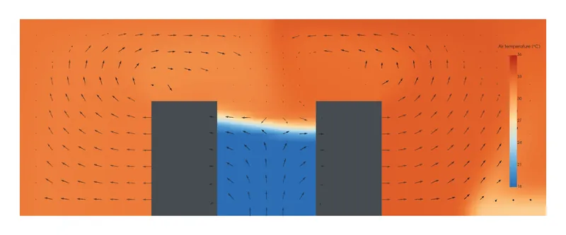
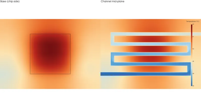
You receive
- Simulation report (PDF / Word, EN or CN)
- 3D contours, sections, streamlines (PNG)
- Key results table (Excel)
- Case files on request
Good to know
- Every assumption (loads, flows, ambient) is listed for your confirmation.
- Interim results are shared; key assumptions are confirmed first.
- Your models and data stay confidential and are never used as samples.
Have a model or a cooling question?
Send your 3D model, equipment data and what you need to know.
Service 3
Engineering calculations
Stand-alone calculations with a clear calculation sheet you can check line by line.
Water systems
Primary and secondary loops: pipe, fitting and equipment pressure drop, parallel branches, pump selection check.
Heat exchangers
Plate heat exchanger sizing and LMTD checks for given temperatures and flows.
Noise
Site-boundary noise and its distribution around the site, checked against your local limit or GB 12348.
Delivered as a calculation report (PDF / Word) with the Excel workings.
Service 4
Technical documents
Written by engineers for the people who install, operate and approve the equipment.
- User manuals and product specifications
- Installation, operation and maintenance manuals
- Flushing and commissioning SOPs
- Engineering reports
- English and Chinese, or both side by side
- Word and PDF
- Open items marked for your confirmation — no invented numbers
Have drawings ready?
Send your DWG plans, the floors and systems in scope, and your deadline.